Best Practices and Patient Comfort with Digital Intraoral Radiography
A Peer-Reviewed Publication
Written by Gail F. Williamson, RDH, MS
Educational Objectives
The overall goal of this article is to provide the reader with information on intraoral digital radiography. Upon completion of this course, the reader will be able to:
- List and describe the types of digital receptors used for intraoral radiographic imaging.
- List and describe the principles of paralleling and bisecting angle techniques for effective and accurate intraoral digital radiography.
- List and describe the adjustments in technique that may be necessary to accommodate anatomy, discomfort and placement difficulties.
- List and describe best practices for patient radiation safety and protection.
- List and describe common errors that occur when taking intraoral digital radiographs and corrections that can be made when errors occur.
Detailed, accurate radiographs are a primary diagnostic tool as well as necessary for and during some treatments. Increasingly, digital radiographic imaging is being used with two types of available receptors. Anatomical variations and patient comfort must be considered when taking intraoral radiographs. In addition, recognizing common sources of errors is important to ensure that the clinician avoids them and knows how to correct them when they occur. Techniques, as well as devices and accessories, can be used that will enable accurate image acquisition and improve patient comfort.
Introduction
Dental radiographs are taken as primary diagnostic tools and for treatment purposes. As such, they must be as detailed and accurate as possible to meet clinical requirements. Increasingly, digital radiography is becoming the technology of choice and offers several advantages over film radiography. These include the ability to view images on the screen, computerized archiving of images, ability to enhance acquired images, reduced exposure to radiation, and rapid acquisition of images without the need for chemical processing. In order to produce high-quality diagnostic images, a careful technique is required that considers best practices and patient comfort. Accurate technique, effective patient management, and proper exposure are required to optimize the information that can be obtained from radiographs and, therefore, their value.
Typically, radiographic examinations are used to evaluate oral disease states such as periodontal disease, caries, and periapical pathology. While for periodontal disease and periapical pathology the radiographic projection of choice is usually a periapical or series of periapical images that record the entire tooth and supporting bone and is of value in diagnosing bony and root pathoses, bitewing radiographs are the radiograph of choice for the detection and monitoring of dental caries in the posterior teeth and can also better detect alveolar bone levels in these sextants. Vertical bitewings (size 1) may also be used to take images of the anterior teeth to assess alveolar bone levels. The patient's medical and dental history, clinical signs and symptoms of disease, risk factors, age and dentition, and new or recall patient status must also be considered when determining which radiographs are required. Recommendations are available for the appropriate patient-specific selection of radiographs (The Selection of Patients for Dental Radiographic Examinations, Revised 2004).1 The overall objective of intraoral radiography is to minimize exposure to radiation while maximizing the diagnostic and interpretative value of the radiographs. The focus of this article is on the use of digital radiography, which in the last two decades has steadily increased.
I. Digital Receptors
Digital receptors are available in two formats: 1) photostimulable phosphor plate (PSP) receptors; or 2) rigid wired or wireless charge-coupled devices (CCD), complementary metal oxide semi-conductors (CMOS) or complementary-metal-oxide semiconductor active pixel sensor (CMOS-APS) receptors. These rigid digital receptors are often referred to as sensors and the term is used interchangeably. Both systems are computer-based technologies that require specific hardware and software components for operation.
Digital receptors are faster than film, which reduces the amount of radiation needed to produce a diagnostic image and eliminate chemical processing errors, darkroom maintenance, and chemical waste disposal. They are available in sizes comparable to film, most typically sizes 0, 1, and 2. Both types of digital receptors are reusable. Therefore, it is important for the clinician to consult the manufacturer's instructions for proper preparation and coverage of the receptor, as well as for effective barrier removal techniques. Care must be taken to avoid direct saliva contact with the receptor and prevent cross-contamination. Disinfection can be accomplished with ADA- or EPA-approved products and typical disinfection techniques followed by coverage with an effective barrier. For rigid receptors, the Centers for Disease Control and Prevention recommends using a double barrier, with both an internal and external barrier.2
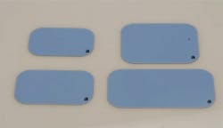
Phosphor plate receptors are more flexible and thinner than rigid digital receptors but have the same dimensions as film. Plate receptors are used much like film but must be handled carefully, scanned to digitize the image, and erased before reuse. Rough handling may produce plate scars, result in image artifacts, and necessitate plate replacement, making them less user friendly in these instances.3 These problems in turn may result in retakes, thereby increasing patients' radiation exposure. Recent improvements in plate technology have been directed toward making plates more scratch resistant to improve longevity, and permitting immediate erasure after scanning to save time.

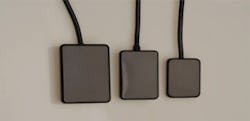
Rigid digital receptors are more difficult to use initially than phosphor plate receptors, and may result in more problems for both periapical and bitewing radiographic images when compared to film. Common issues associated with rigid digital receptors include: 1. placement errors, especially in premolar and molar areas; 2. vertical angulation errors in the anterior regions, resulting in incisal edge cutoffs; 3. horizontal overlapping; 4. cone-cutting; 5. difficulties with bitewing placement, especially premolar views and vertical bitewings; and 6. discomfort.4-7 To avoid these problems, attention to the details of placement in terms of precise location, horizontal and vertical parallelism of the receptor to the structures, and accurate alignment of the x-ray beam are critical. To avoid cutting off incisal edges, a cotton roll can be placed on the biteblock to facilitate placement and allow the crowns to be fully recorded. In addition, rigid receptors should be placed closer to the midline to reduce discomfort and to achieve a parallel rather than angular placement. It is particularly important to employ this approach when a patient has a shallow palate or floor of mouth, both to avoid discomfort and distortion of the image. Typically, rigid sensors have a slightly smaller surface area for recording the image than film does, and this must be taken into consideration during receptor placement. To overcome placement difficulties on premolar and molar periapicals or premolar bitewings, two alternative approaches can be employed. 1. To capture the distal surface of canines, it may be easier to take an additional anterior periapical on each arch to capture the canine-premolar contact. 2. To achieve a more anterior position of a premolar periapical or bitewing or a more posterior placement of a molar periapical, a horizontal offset technique can be utilized. This approach alters the horizontal placement of the receptor toward the area of interest while directing the x-rays through the contacts of the teeth. This is best accomplished visually, with the ring guide removed from the instrument.
Many manufacturers have designed rounded edges and reduced thickness to enhance comfort and ease of placement. Maximizing the diagnostic value of radiographs starts with correct receptor position, ensuring that the x-ray beam is centered and aligned at the correct vertical and horizontal angulations and is exposed at the correct time.
II. Technique Overview
Intraoral radiographic images must be positioned accurately, which can be achieved using an appropriate technique for the desired radiographic projection and anatomical situation. Devices used to accomplish this include receptor instruments with ring guides, standard bite blocks, cotton rolls, and bitewing tabs. The techniques that can be used are the paralleling, bitewing, and bisecting angle techniques.
Paralleling Technique
The paralleling technique is used for both periapical and bitewing radiographs and is the most accurate technique for taking these projections. The digital receptor should be placed vertically and horizontally parallel with the teeth that are being radiographed. The x-ray beam should be directed at right angles to the teeth and receptor.

In the case of periapical radiographs, the digital receptor should be placed parallel to the full length of the crown and root of the teeth being imaged. To achieve the best placement and patient comfort, the digital receptor should be placed closer to the midline rather than close to the teeth. It is helpful to use a cotton roll underneath the biteblock to reduce the need for heavy biting forces that often result in patient discomfort. Technique guidelines call for precise location and inclusion of specific structures on each projection.
Bitewing Technique
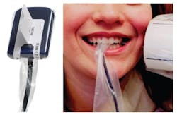
Regardless of approach, instrument, or tab, bitewings are based on the paralleling technique. The digital receptor should be placed vertically and horizontally parallel to the crowns of the teeth. For patients who gag easily or for children, tab bitewings are less cumbersome and more comfortable for the patient. Bitewing tabs hold the digital receptors in position intraorally but provide no external alignment guide for PID (Position Indicating Device, or x-ray cone) positioning and beam direction. Careful placement and beam alignment will produce good results. The vertical angulation is typically set at +5°, with the beam centered to the tab or the center of the receptor. The tab should be aligned with the teeth contacts, which will indicate the correct horizontal angulation to use to enter the contacts. Central ray entry points will help with x-ray beam centering, as will using the lines on the PID that indicate the direction of the x-rays exiting the collimator.
Bisecting Angle Technique
The bisecting angle technique is an alternate approach for periapical radiography. With this technique, the receptor is placed diagonal to the long axis plane of the teeth. The beam is then directed at a right angle to a plane that is midway between (bisects or divides) the receptor and the teeth. This method produces less optimal images because the receptor and teeth are not in the same vertical plane. However, it is a useful method when ideal receptor placement cannot be achieved due to anatomic obstacles or placement difficulties. This technique is more operator-sensitive. If the angle is not correctly divided, elongation or foreshortening will occur. A variety of holders can be used for accurate positioning of the receptor in different locations in the mouth.
One approach the clinician can use is to align the PID parallel to the receptor or external ring guide initially and then reduce the vertical angle by approximately 10°, which will approach the bisecting plane (Table 1). Also, starting angles can be used that will get the operator close to the bisecting plane in each area of the mouth when non-ringed instruments or devices are used. These angles can be aligned using the angle meter on the side of the x-ray head. Application of the bisecting angle technique has become more common in digital radiography with rigid digital receptors. Often it is difficult to achieve true parallelism with the tooth structure; as a result, crowns and apices are frequently cut off due to overangulation. Reducing the vertical angulation compensates for the lack of parallelism to the structures.
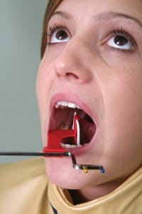
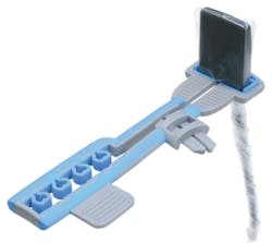
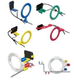
Digital Receptor Instruments
Receptor instruments with x-ray beam ring guides improve the accuracy of the PID alignment to ensure correct beam angulation and centering. Receptor instruments combine a receptor holder with an arm that has an attached ring indicating the position for the PID. This helps the operator avoid cone cut errors by specifically directing the x-ray beam toward the center of the receptor. Regardless of the instrument used, the placement of the receptor relative to the teeth must be correct. Instruments are available for paralleling, bisecting, and bitewing techniques, as well as for endodontic imaging where endodontic files may impede proper positioning of the receptor behind the tooth.
III. Technique Adaptations
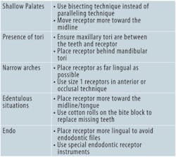
Technique adaptations may be required due to anatomical considerations or to avoid patient discomfort. These anatomical considerations include shallow palates, narrow arches, the presence of tori, and loss of alveolar bone (edentulous ridges). Adaptations may also be required in the presence of endodontic files when radiographs are taken during treatment. Selecting the bisecting angle technique instead of the paralleling technique is useful in the case of shallow palates; careful placement of receptors or the use of special receptor instruments (endodontic imaging) are necessary to accommodate all the listed anatomical variations (Table 2).
IV. Receptor Placement (Paralleling)
V. Patient Comfort
Ensuring that patients are as comfortable as possible while taking radiographs not only helps patients but also results in a greater likelihood of successful imaging and reduced risk of retakes associated with patients moving or altering the position of a digital receptor while the radiograph is being taken. Gagging and discomfort associated with the edges of receptors are key considerations.
Gagging patients can be challenging and require patience and reassurance from the clinician. It is important to be organized, preset the exposure time, pre-align the PID, and be ready to act quickly. The most common area to elicit the gag reflex is the maxillary molar periapical view. Placement of the receptor toward the midline and away from the soft palate will reduce the tendency for gagging. A variety of strategies will help manage the gagging patient: breathing through the nose, salt on the tongue, distraction techniques (lifting one leg in the air, bending the toes toward the body, humming), use of topical anesthetics, and tissue cushions on the receptor.
Similar approaches can be useful when the patient experiences discomfort from the receptor. The use of topical anesthetic agents and receptor cushions improve comfort. Rigid digital receptors can cause more discomfort than other receptors; placing these closer to the midline can reduce patient discomfort. This is especially important in patients with a shallow palate or shallow floor of the mouth, because the edge of the receptor is more likely to dig in as there is less space for positioning and placement of the receptor, and tori necessitate placing the receptor behind them. Using lightweight bite blocks and receptor arms/rings also improves patient comfort. Another option is to use a receptor holder without the accompanying arm and ring, allowing for positioning of the sensor that optimizes patient comfort without compromising accuracy; this requires knowledge of the bisecting angle technique and is useful when positioning must accommodate anatomical variations as described above.
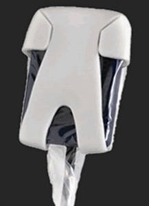
In bitewing radiography, tabs can be used and are usually less uncomfortable for the patient, although the edges of a rigid receptor may still be a potential source of discomfort. While regular bitewing tabs are more comfortable, they are less reliable than the use of a holding device because they may allow movement or displacement of the sensor. Bitewing tabs with extended straps that wrap around the sensor solve this problem and keep the tab positioned exactly in the center of the sensor and the barrier cover without compromising patient comfort. Self-adhesive foam covers can be used over the receptor for both bitewings and periapicals to smooth the edges and provide cushioning against the patient's oral mucosa.
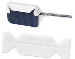
Another option is the use of foam covers that fit over all edges of the receptor and have soft, pliable edges. When adhesive holders are used, keeping the sensor firmly within the sensor barrier is critical and can be achieved by using a thin foam layer designed for this purpose that precisely fits over the sensor barrier. Since this is constructed of soft foam, it also aids patient comfort.
In addition, instructing the patient to "lightly" or "gently" bite just hard enough to keep the sensor in place and stable also aids comfort and serves to maintain proper positioning and alignment.
Regardless of techniques accommodating patient comfort and anatomy, accuracy of positioning must be maintained to avoid errors and retakes that expose patients to unnecessary radiation and potential discomfort. Poor positioning is a common source of errors in radiography.
VI. Patient Protection
Patients tend to be more cooperative and receptive to radiographic procedures when radiation protection is provided. Patient protection includes the use of lead collars and lead aprons during radiographic imaging procedures. Lead collars are designed to protect the thyroid. These collars have been found to substantially reduce radiation to the thyroid during dental radiographic examinations.8 There are varying perspectives on the necessity of lead aprons and thyroid collar shields. Selection criteria guidelines recommend that all precautions should be taken and patient shielding be provided whenever possible, particularly for children, women of childbearing age, and pregnant women.1 The National Council on Radiation Protection (NCRP) Report 145, Radiation Protection in Dentistry, states that if all the safety measures outlined in the report are rigorously followed, a lead apron is not required.9 However, the radiation safety measures include rectangular collimation of the x-ray beam, use of fast image receptors, application of selection criteria, and a variety of other standards that all must be in place in order to eliminate the use of the lead apron. In addition, NCRP Report 145 states that thyroid collars shall be provided for children and should be provided for adults except when they interfere with examination, as in the case of panoramic imaging.9 Therefore, best practices include the use of lead aprons and thyroid collars and other safety measures that help the clinician comply with the ALARA (As Low As Reasonably Achievable) principle and keep the patient's exposure to a minimum.
Also, the clinician must remember that the lead contained in lead aprons and collars is thin and malleable, and if the apron or collar is folded or improperly stored, the lead can be bent and damaged such that it compromises protection. Collars and aprons should be hung up to avoid damage. As an alternative to leaded aprons, lightweight options are available that incorporate materials that effectively absorb the scatter radiation but are not as heavy or ungainly to use, and may be more comfortable for patients.10
VII. Common Errors
When the principles of radiographic technique are not applied, technical errors will occur. Errors need to be identified, understood, and corrected so that they do not continue to occur. The most typical technique errors occur in placement, vertical angulation, horizontal angulation, x-ray beam centering, and exposure.
Placement errors occur when the clinician fails to properly place the receptor to record the correct teeth, or cuts off the crowns or apices of teeth.
Vertical angulation errors distort the length of the structures and result in either foreshortening or elongation. Foreshortening requires a decrease in the vertical angle for correction; elongation requires an increase in the vertical angle. Vertical angulation errors are more common with the bisecting angle technique than with the paralleling technique. However, vertical angulation errors, especially elongation, can occur with the paralleling technique when the patient bites too forcefully and torques or flexes the receptor out of the correct vertical position. To correct, ensure light biting pressure with the use of a cotton roll under the biteblock, and use lingual placement away from the teeth with receptor, teeth, and PID all parallel to each other.
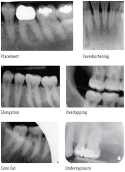
Horizontal angulation errors result in overlapping of proximal surfaces and limit caries and bone loss evaluations. To correct, the horizontal angle must be directed through the proximal surfaces of the teeth. It is helpful to align the lateral sides of the biteblock parallel with the teeth contacts to better guide the x-rays through the proximal contacts of the teeth. Overlapping occurs more commonly with tab bitewings. However, overlapping can occur with bitewing instruments if the receptor is not placed parallel to the horizontal plane of the teeth.
Cone cut errors are caused by not centering the x-ray beam over the receptor. Lack of centering produces partial exposure of the receptor with a "cut" where x-rays did not interact with the receptor. Receptor instruments with beam guides facilitate beam centering over the receptor when properly assembled.
Exposure errors result in light or dark images due to improper exposure time or lack of consideration of patient size and the thickness of structures. Underexposures cannot be corrected with software enhancements, but overexposures can usually be adjusted to moderate image density.

VIII. Summary
Dental radiographs are valuable diagnostic tools and expose the patient to minimal amounts of radiation. Nonetheless, dental professionals must ensure that patients are protected from the harmful effects of cumulative exposure to radiation. Patients can be protected through the use of lead collars and aprons and by ensuring that only necessary radiographs are taken and that radiation exposure is kept low. Patient comfort can be improved by placing digital receptors in a position that allows for accurate radiographs as well as using devices and accessories that improve patient comfort. One of the critical factors in minimizing the number of radiographs is to ensure that retakes are not required due to improper technique or patient management. Receptor instruments are valuable tools that guide the x-ray beam and thereby assist in the accuracy of dental radiographic images.
Selected References
1. American Dental Association and U.S. Department of Health and Human Services. The Selection of Patients for Dental Radiographic Examination, Revised 2004.
2. Centers for Disease Control and Prevention. Guide¬lines for infection control in dental health-care settings 2003. MMWR 2003;52(RR-17):1-68.
3. Bedard A, Davis TD, Angelopoulos, C. Storage phosphor plates: How durable are they as a digital dental radiographic system? J Contemp Dent Pract 2004;5:057-069.
4. Matzen LH, Christensen J, Wenzel A. Patient discomfort and retakes in periapical examination of mandibular third molars using digital receptors. Oral Surg Oral Med Oral Pathol Oral Radiol Endod 2009;107:566-572.
5. Versteeg CH, et al. An evaluation of periapical radiography with a charge-coupled device. Dentomaxillofac Radiol 1998;27:97-101.
6. Sommers TM, Mauriello SM, Ludlow JB, Platin E, Tyndall DA. Pre-clinical performance comparing film and CCD-based systems. J Dent Hyg 2002;76:26-33.
7. Bahrami G, Hagstrom C, Wenzel A. Bitewing examination with four digital receptors. Dentomaxillofac Radiol 2003;32:317-321.
8. Sikorski PA, Taylor KW. The effectiveness of the thyroid shield in dental radiology. Oral Surg.1984;58:225-236.
9. National Council on Radiation Protection and Measurements. Radiation Protection in Dentistry. NCRP Report No. 145. Bethesda, MD. NCRP 2003, Revised 2004;14-27.
10. Williamson GF. Intraoral Radiography: Positioning and Radiation Protection. Academy of Dental Therapeutics and Stomatology, Chesterland, OH, 2007.
Author Profile
Gail F. Williamson, RDH, BS, MS, is a professor of Dental Diagnostic Sciences in the Department of Oral Pathology, Medicine and Radiology at Indiana University School of Dentistry in Indianapolis, Indiana. She received an A.S. in Dental Hygiene, a B.S. in Allied Health, and a M.S. in Education, all from Indiana University. She serves as Director of Allied Dental Radiology and Course Director for Dental Assisting and Dental Hygiene Radiology courses. A veteran teacher, Prof. Williamson has received numerous awards for teaching excellence throughout her career. She is a published author and presents numerous continuing education courses on Oral and Maxillofacial Radiology on the national level. In addition, she is actively involved in the American Academy of Oral and Maxillofacial Radiology and currently serves as a radiology expert on the American Dental Association's Dental Hygiene National Board Test Construction Committee B.
Disclaimer
The author of this course has no commercial ties with the sponsors or the providers of the unrestricted educational grant for this course.
Reader Feedback
We encourage your comments on this or any PennWell course. For your convenience, an online feedback form is available at www.ineedce.com.
Use this page to review the questions and answers. Return to www.ineedce.com and sign in. If you have not previously purchased the program select it from the "Online Courses" listing and complete the online purchase. Once purchased the exam will be added to your Archives page where a Take Exam link will be provided. Click on the "Take Exam" link, complete all the program questions and submit your answers. An immediate grade report will be provided and upon receiving a passing grade your "Verification Form" will be provided immediately for viewing and/or printing. Verification Forms can be viewed and/or printed anytime in the future by returning to the site, sign in and return to your Archives Page.
Questions
1. Dental radiographs are taken ________
- for treatment purposes
- as primary diagnostic tools
- as definitive tools
- a and b
- Computerized archiving of images
- The ability to enhance acquired images
- Rapid acquisition of images without the need for chemical processing
- all of the above
- a series of bitewing images
- a series of periapical images
- a series of periapical and bitewing images
- none of the above
- rigid wired or wireless charge-coupled devices
- photostimulable phosphor plate (PSP) receptors
- complementary metal oxide semi-conductors or complementary-metal-oxide semiconductor active pixel sensor receptors
- all of the above
- using a single barrier, with an external barrier
- using a single barrier, with an internal barrier
- using a double barrier, with both an internal and external barrier
- using a single barrier, with both an internal and external barrier
- are more flexible than rigid receptors
- are thinner than rigid receptors
- have the same dimensions as film
- all of the above
- canine-lateral incisor contact
- premolar-premolar contact
- canine-premolar contact
- all of the above
- periapical
- bitewing
- panoramic
- a and b
- perpendicular
- at an acute angle
- at right angles
- at an obtuse angle
- less convenient
- less cumbersome
- more comfortable
- b and c
- positioning of the sensor plate
- x-ray beam reduction
- x-ray beam lateralization
- x-ray beam centering
- bitewing radiography
- periapical radiography
- occlusal radiography
- all of the above
- rigid digital receptors
- flexible digital receptors
- flexible x-ray film
- none of the above
- +15° to +25°
- -15° to - 25°
- +25° to +35°
- -25° to -35°
- +10° to +15°
- +15° to +25°
- -10° to -15°
- -15° to -25°
- corner of the mouth
- ala of the nose
- tip of the nose
- none of the above
- horizontal placement
- vertical placement
- diagonal placement
- any of the above
- horizontal placement
- vertical placement
- diagonal placement
- horizontal or vertical placement
- due to anatomical considerations
- in the presence of endodontic files
- to avoid patient discomfort
- all of the above
- use the bisecting technique instead of the paralleling technique and move the receptor more towards the midline
- use the paralleling technique instead of the bisecting technique and move the receptor farther from the midline
- use the paralleling technique instead of the bisecting technique and move the receptor more towards the midline
- use the bisecting technique instead of paralleling technique and move the receptor farther from the midline
- be organized
- preset the exposure time and pre-align the PID
- be ready to act quickly
- all of the above
- maxillary molar periapical
- mandibular molar periapical
- maxillary incisor periapical
- mandibular incisor periapical
- receptor cushions
- topical anesthetic agents
- lightweight bite blocks
- all of the above
- over the receptor for bitewings
- over the receptor for periapicals
- to smooth the edges and provide cushioning
- all of the above
- a thin foam layer
- a thick foam layer
- a thin polystyrene layer
- a thick polystyrene layer
- are designed to protect the thyroid
- substantially reduce radiation to the thyroid
- is a best practice together with the use of lead aprons
- all of the above
- As Level As Reasonably Achievable
- As Low As Reasonably Acceptable
- As Low As Reasonably Achievable
- none of the above
- distort the length of the structures
- result in either foreshortening or elongation
- are more common in bisecting angle technique than with paralleling technique
- all of the above
- overlapping of proximal surfaces
- limit caries evaluations
- limit bone loss evaluations
- all of the above
- increasing the vertical angulation of the PID
- centering the x-ray beam over the image receptor
- decreasing the vertical angulation of the x-ray beam
- directing the x-rays between the contacts of the teeth